V5.339 Illustrated Operation Manual
This is the complete self-service guide for drawing or importing a room, adding openings, defining cabinet runs, operating blind-corner solutions, designing islands and peninsulas, generating cabinets, fixing blocking geometry errors, reviewing amber planning guidance, saving the project, and reviewing the kitchen in 3D.
Every image on this page was captured from the live V5 interface. Menu names in the steps match the buttons you will see in the software.
1. Fast start: the correct operating order
Use this order for every new kitchen. Defining the room and cabinet intent before generation prevents most corner, opening, and filler problems.
Load, draw, or import the shell.
Add doors, windows, and wall openings.
Place Base and Wall zones.
Reserve sink, stove, fridge, island, or tall cabinets.
Choose RTA or Custom, then generate cabinets.
Fix pink errors and review amber guidance.
Inspect, report, and save the editable design.
2. Know the V5.339 screen
View controls: Floorplan, Zones, and Cabinets are icon buttons in the upper-right corner of the 2D floor plan header. Hover or focus an icon for its label. Open Elevation from the Views bar. Report sits beside Files and Save in the top toolbar. Open Preferences for Cabinet Height and Ceiling Height; the second toolbar has been removed.
Select, Pan, Fit, Undo, Redo, and Delete stay visible. Auto Design opens proposal previews directly; Generate Cabinets creates the cabinet layout. Files and Save are at the top right.
The single command row includes Room, Door, Window, Opening, Base, Wall, Tall, Island, Sink, Stove, Fridge, and four corner families: Base L, Base Blind, Wall Diagonal, and Wall Blind. Blind width and Left/Right access choices appear in a visible settings strip; Wall blind also offers 30/36/42-inch height. In 3D the placement tools become finishing and accessory tools. On narrow screens, use the left/right arrows to scroll along the same row. Floorplan / Zones / Cabinets are icons in the 2D panel header. Open Elevation from Views, Report from the top toolbar, and both height settings from Preferences.
The creation rail is on the left, working controls are across the top, the canvas is in the center, and support controls are at the upper-right.
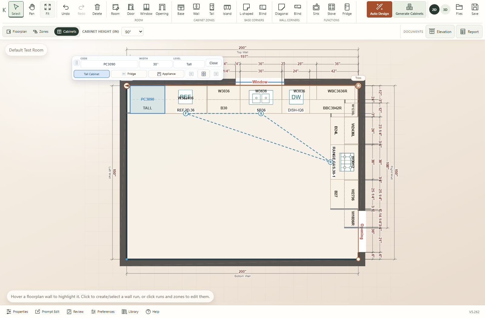
| 2D stage | What you see and edit | Use it for |
|---|---|---|
| Floorplan | The imported or drawn room shell, wall lengths, Doors, Windows, and full-height Openings. Cabinet intent and generated output are retained but hidden. | Verify Joyplan scale and orientation; correct wall/opening geometry before cabinetry. |
| Zones | Base, Wall, and Tall placement spans plus Sink, Stove, Fridge, island, peninsula, and protected junction intent. | Change where cabinetry is allowed and where fixed kitchen functions must remain. Regenerate after an intent change. |
| Cabinets | The generated cabinet-by-cabinet result, codes, widths, fillers, panels, appliances, and dimension chains. Thin red lines show countertop edges, cyan lines show toe kicks, and green lines show top molding. | Review and edit individual generated items. The finish outlines update with the layout. Return to Zones when the underlying run or function intent is wrong. |
| Wall stacking | Preferences → Wall stacking → To ceiling adds a 12″, 15″ or 18″ upper tier when it fits after 3″ crown. A 108″ ceiling and 90″ cabinet top use a 15″ stack. Tall and refrigerator stacks keep 24″ depth. |
| Area | Purpose |
|---|---|
| File | Open the File menu at the top right. Save or reopen a design, open a GLB floor plan, import Joyplan DAE, or copy planner JSON. |
| Select | Normal editing mode. Select walls, zones, openings, corners, generated cabinets, fillers, panels, islands, and peninsulas. |
| Room | Create the default rectangle or draw a custom room shell. |
| Openings | Place Door, Window, or Opening on a wall. |
| Runs | Place Base or Wall cabinet zones and choose the next Base depth. |
| Functions | Reserve Sink, Stove, Fridge, Island, or Tall Cabinet Area. |
| Corners | Place supported LS3612 base or WDC2436 wall corner cabinets. |
| Preferences | Set the default width for newly placed Sink, Stove, and Fridge areas; choose RTA/Custom; and optionally request one/two 9" stove-side cabinets or a 15"/18" waste-bin cabinet. |
| Top controls | Generate cabinets, switch 2D/3D, open Report, and fit the confirmed Kitchen Area. Use the 2D panel header for Floorplan/Zones/Cabinets, Preferences for height settings, and the bottom bar for Help and the current version. If no Kitchen Area exists, Fit frames the complete plan. Files is at the top right; Prompt Edit is on the bottom bar. |
4. Create the room and openings
Room menu

- Click Room.
- Choose Rectangular for a quick editable shell, or Draw for a custom perimeter.
- For Draw, click each corner in order. Press Enter or right-click to finish; press Esc to cancel.
- Return to Select, click a wall, and edit its length/height or add a short wall where supported.
- Use Fit whenever the room is partly outside the canvas.
Columns
Drag Column from the Room tools into the room, or click the tool and then click the plan. The default footprint is 24″ × 24″; height follows Ceiling Height automatically. Move it near a right-angle room corner to snap flush to both walls. Select the column and drag any edge to resize width or depth while keeping the opposite edge fixed. Use Dimensions or click a column dimension to enter inches, decimals, or fractions. Dimensions preserve a snapped corner. Wall-touching column faces join the continuous door/window/building-element dimension chain, including the gaps between elements and the remaining wall. Corner columns appear in both adjacent wall chains; the overall wall length remains outside. Column dimensions stay visible without selection and can be clicked or tapped to edit. Undo/Redo, Delete, Save/Open and 3D retain columns. Columns are solid obstacles: placement zones stop beside their footprint, with space for adjacent fillers. Drop on either side of a middle-of-wall column to use that clear span. Moving or resizing a column adjusts existing zones and generated cabinets; an edit is rejected if no usable space remains. Zone dragging, edge resizing, dimension edits, and Auto Fill keep clear of columns.
Openings menu

- Click Openings.
- Drag the required item onto a wall and release when the wall highlight appears.
- Click the placed item to edit width, opening height, sill height, and left/right wall offsets.
- Place openings before cabinet zones so generation can reserve safe cabinet spans.
5. Define cabinet runs and function zones


Place Base and Wall zones
- Click Runs.
- Set Next Base depth before the drag when a depth other than 24" is required. Accepted catalog depth is 12"–36".
- Drag Base onto the inside face of a wall. The floating edit window shows Start, Length, End, and Depth.
- Drag Wall zone onto the same wall where upper cabinets are allowed.
- Use the end handles or edit-window values to shorten a zone. Fractions such as
30 1/2are accepted.
Reserve appliance and tall-cabinet intent
- Open Preferences first when the next function should use a non-default width. Sink/Fridge support 30", 33", and 36"; Stove supports 24", 30", and 36". The established defaults are 36", 30", and 36" respectively.
- Under Auto Design tall program, optionally select Pantry and/or Appliance. Both are unchecked by default. Auto Design always treats Fridge as primary and keeps every selected tall unit together with it as one contiguous block at the end of a wall run.
- Use the visible Sink, Stove, and Fridge tools.
- Drag Sink, Stove, or Fridge onto an existing Base run. The new area uses the selected preference width.
- Click an existing function to choose a different width in its floating editor; preference changes never resize existing areas.
- Drag Tall Cabinet Area to reserve pantry/full-height cabinetry, or drag Island area into free floor space and edit its length, depth, rotation, and clearances.

6. Generate cabinets and edit the result
Complete Preferences setup
Open Preferences and choose RTA or Custom under Cabinet system. The dark button is the active system. The selection is saved with the editable kitchen project and applies to every generated Base and Wall run.
| Preference | Choices and default | When it takes effect |
|---|---|---|
| Cabinet system | Custom is the new-plan default; choose RTA for exact catalog cabinet bodies. Here Custom means semi-custom reduce-only balancing, not unrestricted full-custom fabrication. | Switching RTA/Custom immediately recalculates every eligible generated run and is saved with this project. |
| Next Sink width | 30", 33", or 36"; default 36". | Applies only to the next newly placed Sink. Edit an existing Sink in its own floating editor. |
| Next Stove width | 24", 30", or 36"; default 30". | Applies only to the next newly placed Stove. |
| Next Fridge width | 30", 33", or 36"; default 36". | Applies only to the next newly placed Fridge. |
| Stove-side B9 | Blank, one 9" cabinet, or two 9" cabinets; blank by default. | Applied by the next Generate Cabinets. Click the active option again to clear it. |
| Waste-bin cabinet | Blank, 15", or 18"; blank by default. | Applied by the next Generate Cabinets. Click the active option again to clear it. |
| Show design review overlay | Under Design validation display; off by default. | Shows or hides numbered pink errors, amber guidance, and their separate Design check counts on this device. Matching plan and list numbers identify the same finding. Detection continues and the setting is excluded from customer project files. |
| Show Auto Design preview | Under Advanced features; off by default. | Stores the device-local preview preference. The always-visible Auto Design button enables and opens its preview directly; this preference is not saved in customer projects. |
| Auto Design Pantry / Appliance | Under Auto Design tall program; both unchecked by default. | Project-level Auto Design intent. Selected units are required in proposals and remain contiguous with the primary Fridge at a wall-run endpoint. |
.kitchen.json. The design review overlay and Auto Design preview are device-local and excluded from the project file. Existing function zones never resize just because a default changes. 12
 12
| Setting | Use it when | How V5.238 fills an odd segment |
|---|---|---|
| RTA | The order must use fixed ready-to-assemble catalog cabinet sizes. | Cabinet bodies remain at supported catalog widths. Remaining space is assigned to legal 1 1/2"–3" fit fillers; V5.238 consolidates them at physical endpoints where possible and avoids adjacent fillers. |
| Custom | The cabinet line permits a standard cabinet to be reduced to a job-specific width. | Each fill segment may use one balancing cabinet cut down from the next larger supported catalog cabinet. The cabinet code identifies the source cabinet while the plan/report dimension identifies its actual finished width. |
RTA setup workflow
- Complete the room, openings, Base/Wall runs, functions, and intended corner solution.
- Open Preferences and click RTA under Cabinet system. The RTA button becomes dark.
- If cabinets already exist, the mode switch immediately recalculates all runs once. If this is a new plan, click Generate Cabinets.
- Review every cabinet width against the supported catalog sizes. Review each filler dimension; an ordinary RTA fit filler must remain between 1 1/2" and 3". A structural blind-corner filler remains exactly 3".
- Check that fillers are at usable endpoints where possible, are not placed consecutively, and do not displace a sink, stove, refrigerator, panel, or corner cabinet.
- Open Report in 3D and confirm that the cabinet codes, quantities, filler widths, and total run length match the 2D dimensions.
Custom setup workflow
- Complete the same room, run, function, and corner setup used for RTA.
- Open Preferences and click Custom under Cabinet system. Custom is already active by default for a new plan.
- If cabinets already exist, the switch immediately replaces the RTA fit calculation with the Custom calculation. Otherwise click Generate Cabinets.
- Locate the one balancing cabinet in each odd fill segment. Its actual width may be non-standard, but it is reduced from—not enlarged beyond—the next larger supported catalog source cabinet.
- Confirm the actual cut width in the 2D dimension chain and Report. Use the cabinet code as the source/SKU reference and the displayed actual width as the fabrication dimension.
- Review doors, drawers, adjacent appliances, panels, and corner clearances before saving or producing the order report.
Switch an existing plan safely
- Click Save before changing systems if the current cabinet solution must remain recoverable.
- Open Preferences and click the other system. All existing runs recalculate immediately; a second Generate click is not required for the switch itself.
- Compare cabinet codes, actual widths, fillers, blind-corner ownership, and dimension totals. The layout should change, but the room, run extents, and fixed functions should remain in place.
- After any later zone or function edit, click Generate Cabinets again using the currently selected system.
- Save the revised project under a new filename when both RTA and Custom alternatives must be retained.
Generate
- Confirm room, openings, zones, functions, corners, and the active RTA/Custom setting.
- Click the orange Generate Cabinets button.
- Review cabinet codes, actual widths, filler sizes, and dimension chains in 2D.
- If you change a zone, function, or corner, generate again. Generation is designed to remain stable across repeated runs.

UNRESOLVED space for the designer to correct.Edit a generated cabinet

| Action | Operation |
|---|---|
| Select | Click a generated Base or Wall cabinet. Wall cabinets remain selectable even when no base cabinet is below. |
| Resize | Drag an end handle; an adjacent editable cabinet compensates where supported. Double-click to type an exact width. |
| Swap order | Drag the selected cabinet body over an adjacent editable cabinet. Appliances, fillers, panels, and corners remain fixed boundaries. |
| Split icon | The divided-cabinet symbol creates two legal cabinet blocks while preserving the exact imperial span. Hover or focus the icon to read its name. |
| ▲ / ▼ | Round the selected cabinet up/down to a whole inch. Up retains the wall-filler rules; down reduces the run at an exposed end and is disabled with fillers at both ends. |
| M / E | Select the first cabinet, press M or E, then select the second. M merges the first into the second; E matches the second width to the first. Nonadjacent cabinets are supported when the resulting layout fits. |
| Copy / Delete | Use the floating placement editor to duplicate or remove supported zones and objects. |
| Review intent | Switch to Zones to inspect or correct placement and function areas; existing generated cabinets are retained but hidden. |
| Review output | Switch to Cabinets to select, resize, reorder, split, or merge the generated cabinet result. |
Edit, drag, resize, or convert Tall Cabinet Area modules
 123
 12
 12
 12
- Open Functions, drag Tall Cabinet Area onto a wall, and set the overall length. The Tall Area boundary snaps in 30" increments.
- Click Generate Cabinets. A 60" Tall Area initially becomes two independently editable 30" Tall modules.
- Return to Select and click one cabinet body inside the Tall Area. Confirm the floating cabinet window says Level: Tall and shows Tall Cabinet, Fridge, and Appliance.
- Drag the cabinet body over an adjacent editable Tall module to exchange their positions. Fillers, panels, refrigerators, and appliance modules remain fixed boundaries.
- Drag either width handle to resize the selected Tall cabinet. The adjacent editable Tall module compensates so the Tall Area keeps the same total length; the cabinet codes and displayed widths update immediately.
- Click Fridge to convert a valid 30", 33", or 36" Tall module. V5.238 uses the matching refrigerator model and automatically adds its matching 24"-deep cabinet above.
- Appliance requires exactly 30". If Appliance is disabled, first convert the item to Tall Cabinet and drag-resize it to 30". Then click Appliance. The active 84", 90", or 96" kitchen height selects SO3084, SO3090, or SO3096.
- To undo a conversion without moving the module, click Tall Cabinet. Structural Split/Merge and width-resize controls become available again where neighboring Tall modules permit them.
- Open 3D and verify the refrigerator/top cabinet or SO oven model, full-height panels, fillers, and cabinet height. Save the editable project after the 2D and 3D results agree.
7. Design validation: blocking errors and planning guidance
Use the Design check after every meaningful change
- Complete the room, openings, zones, functions, and cabinet-system preferences, then click Generate Cabinets.
- Open Preferences → Design validation display and enable Show design review overlay. Read the separate pink-error and amber-warning counts. Hover any numbered plan marker to read that finding beside the cabinet. Click the marker or its matching entry under Review numbered findings to open Guided repair with the measured gap, required cabinet width, shortage, affected run, and available repair actions. Drag the review panel heading or dotted grip to move it; use −/+ to collapse or restore it without hiding markers.
- Match each listed finding to its same-number plan marker. Pink means repair the geometry or physical-operation conflict. Amber means compare the advisory target with the customer brief and record the designer decision.
- Use Floorplan for wall, door, window, and opening corrections; Zones for placement intent, functions, islands, peninsulas, and clearances; and Cabinets for generated gaps, widths, and collisions.
- For an UNRESOLVED blind corner, use Show affected run to locate it. When a compatible explicit LS3612 already occupies that physical corner, choose Use LS3612 + refill gap; the planner reconnects the corner, preserves the neighboring function, and re-solves only that run. Choose Move Sink/Stove/Fridge area when space must be redesigned. Every guided repair supports Undo and Redo.
- Regenerate whenever run or function intent changes. Do not approve while any pink error remains; amber guidance may remain only after explicit designer review.
- Perform the 3D door/drawer/appliance-operation review, confirm local requirements, and save the editable project.
| Color and finding | What the planner checks | Where to correct or review it |
|---|---|---|
| Pink — UNRESOLVED, run, opening, or zone failure | Unfilled cabinet spans, placements outside a run, zones crossing an opening, or overlapping placement zones. A blind-corner finding reports its exact available width, required reservation, and shortage. | Click the numbered finding for Guided repair. Reconnect a compatible explicit corner and refill the affected run, show the run, or move the adjacent function; otherwise correct the host intent in Zones and regenerate. |
| Pink — cabinet collision | Two cabinet/appliance footprints overlap at the same vertical range. | Move or resize the affected generated item, or revise the underlying Zones. |
| Pink — door or cooking-window conflict | Cabinetry enters an entry-door swing, or a cooking surface overlaps an operable window. | Correct the opening in Floorplan or relocate cabinetry/functions in Zones. |
| Amber — work aisle or walkway | A work aisle is below the current 42" single-cook reference or a walkway is below 36". | Compare with traffic and customer needs; move/resize the island or peninsula when adjustment is appropriate. |
| Amber — work triangle | The complete triangle joins the room-facing front centers of Fridge, Sink, and Stove. A primary leg is outside 4–9 ft, the total exceeds 26 ft, or a leg crosses an obstacle by more than 12". | Review workflow and traffic; relocate functions or obstructions when that improves the customer plan. |
| Amber — landing or dishwasher guidance | Sink, cooking, or refrigerator landing frontage is short, or the nearest dishwasher edge is over 36" from the sink. Continuous counter includes a built-in dishwasher top and connected Base-corner counter; a narrow refrigerator end panel is crossed but not counted. | Review the appliance model and customer workflow, then rebalance adjacent Base cabinets if needed. |
8. Kitchen layout planner logic
Generate Cabinets is a constraint solver: it measures the usable pieces of every run after walls, openings, protected functions, panels, peninsula junctions, and corner reservations. Each protected reservation splits a run into independent segments. The planner fills those measured segments without silently moving or shrinking fixed kitchen functions.
| Rule | V5.238 behavior | Designer check |
|---|---|---|
| Sink under a Window | Normal placement snaps the Sink center exactly to the same-wall Window center. A saved Sink center within 1" is accepted and preserved during generation. The same tolerance around the nominal 1" Wall-cabinet endpoint gap permits 0"–2", but a cabinet may never overlap the Window opening. | The 1" value is a center/gap tolerance, not permission to overlap a Window. Repeated generation must not accumulate the offset. |
| Sink + dishwasher | Every generated kitchen that contains a Sink receives exactly one 24" DISH-IQ6. The solver first tests zero-gap intervals immediately left and right of the Sink on that same Base run, island, or peninsula as complete layout bundles. Right is only the deterministic tie-break when both bundles are otherwise equal. | Expect direct adjacency whenever either side is legal. The Sink width and released position remain fixed. |
| Dishwasher fallback | Only when neither adjacent side is legal does the solver search connected or nearby Base runs within 96" travel. It excludes openings, other functions/appliances, peninsula junctions, corner blocks, and blind-corner footprints. A legal manual dishwasher drag is authoritative and persists through Save/Open/Generate until it becomes illegal. | If no legal 24" interval exists, the dishwasher is explicitly unresolved; the planner never shrinks the Sink or inserts the dishwasher into a corner. |
| Blind-corner bundle | The starting Base blind solution is BBC4245: a 42" body plus a separate 3" wall distance. While unlocked, the solver may compare BBC3942/BBC4245/BBC4548, 3"–6" wall distance, dishwasher side, Sink/Window tolerance, and fillers as complete bundles. | A supported blind body is only 39", 42", or 45". Its entire body plus clearance must fit without crossing a protected interval. |
| BF336 / BCF3 fallback | BF336 is legal only as the exact 3" structural filler of a supported blind-corner assembly. If no full supported blind cabinet fits, generation removes the blind/BF336 combination and uses BCF3: exact 27" setbacks on both 24" cabinet faces plus the local 3" × 3" angle filler. | Check 27" from the physical inside wall corner in both directions, plus continuous countertop and toe kick. There must be no leftover blind cabinet or BF336. |
| RTA fit | Cabinet bodies keep exact catalog widths. An ordinary residual fit filler is 1 1/2"–3"; at most two may occur in one contiguous protected segment, and two fillers may not be adjacent. | An RTA cabinet is never silently changed to a custom width. Structural corner filler rules remain separate. |
| Custom fit | Custom is semi-custom: each protected segment may use at most one ordinary straight balancing cabinet, reduced from the next supported source size and never enlarged beyond it. | Use the displayed actual width for fabrication and the cabinet code as the source reference. |
| User locks and failure | A direct Sink, Stove, Fridge, dishwasher, blind-size, or blind-distance choice locks that intent. Remaining unlocked values re-solve around it. If a legal layout cannot honor the fixed choice, the affected span is dashed UNRESOLVED and is excluded from 3D. | Correct the zone/function/corner intent; do not treat UNRESOLVED as a generated cabinet. |
| Openings and exposed ends | A Base zone stops 1" clear of a Door or full-height Opening. A newly exposed end uses a 3/4" finish panel, and door-split segments solve independently. | Confirm that the cabinet/panel does not consume the opposite side of the opening. |
| Single-door handing | Single-door cabinets to the left of a Sink or Stove open left; cabinets to the right open right. Handing follows run order, not left/right on the page. | Check the physical run direction whenever the plan is rotated. |
How the solver chooses among legal bundles
- Reject overlaps and missing required components.
- Require exactly one dishwasher for a generated Sink and prefer direct adjacency.
- Avoid unresolved spans, then prefer fewer/smaller fillers and the smaller Sink-to-Window offset.
- Prefer the solution closest to the default corner bundle; deterministic tie-breaks keep repeated generation stable.
9. Corner solutions, blind cabinets, island, and peninsula
Understand the corner solution editor
 123
- Create two compatible Base runs that meet at a real inside wall corner, then click Generate Cabinets. For upper cabinets, create two compatible Wall zones.
- Return to Select and click the generated blind-corner cabinet body. The floating Corner solution group shows the current owner and all valid replacements.
- The current Base choice is shown like Blind R on Top Wall. The alternate button is shown like Blind L on Right Wall. Click the alternate wall to move ownership to that run; the visible L/R handing changes automatically and both runs realign.
- The selected catalog width and separate wall clearance follow the cabinet to its new owner. For example, a 42" BBC4245 plus 3" clearance occupies the complete 45" physical-corner interval; a relocated dishwasher may use another legal run but may not shorten or overlap that reservation.
- For Wall zones, the same operation switches the WBC blind cabinet between the two connected Wall runs.
- After every switch, verify the cabinet door/open side faces the usable run and that the yielding perpendicular run contains the correct filler rather than a second corner cabinet.
UNRESOLVED instead of drawing a shortened BBC cabinet.Move the blind corner and resize its cabinet
| Action | Exact operation and result |
|---|---|
| Move / change wall distance | Drag the body of the selected blind-corner cabinet along its owner run. V5.238 changes the wall-clearance value between 3" and 6"; it does not reorder the cabinet or detach it from the corner. |
| Resize Base blind cabinet | Drag the selected cabinet's side width handle. The result snaps to supported Base blind cabinet widths 39", 42", or 45"; the code and total corner span update together. |
| Resize Wall blind cabinet | Drag the width handle on a WBC result. Supported Wall blind widths are 30", 33", or 36". |
| Exact distance by prompt | Click Prompt Edit on the bottom bar, enter an instruction such as Set the selected blind corner distance to 4 1/2 inches., then click Apply Design Edit. |
| Cancel a drag | Press Esc before release. Reopen Select and click the blind body if a wall or placement was selected instead. |
Drop LS3612 or WDC2436 onto an existing blind corner
- Open Corners. Choose LS3612 for a Base corner or WDC2436 for a Wall-cabinet corner.
- Start the drag from the palette tile and move over the existing generated blind-corner footprint, not merely an empty wall point.
- Release when the target corner preview/highlight appears. V5.238 replaces the blind solution with one explicit corner cabinet and re-solves both connected layouts; it does not stack a second cabinet over the blind.
- Click the new LS3612/WDC2436. Its floating editor offers Blind R on … and Blind L on … buttons for the two connected runs, so the replacement is reversible.
- Confirm there is one corner cabinet, no duplicate blind cabinet, no
UNRESOLVEDgap, and no internal finish panel at the connected joint.
LS3612 Base corner
Use at a true inside Base corner. It reserves both legs and replaces the BBC blind result at that point.
WDC2436 Wall corner
Use where two Wall zones meet. It replaces the WBC result and keeps both Wall layouts aligned.
BF336 straight filler
The normal 3" joining filler between a yielding run and the corner structure. Select the filler itself to open its separate accessory editor.
BCF3 angle filler
Choose BCF3 in the filler editor for the 3" × 3" L-shaped joint. For two 24"-deep runs it maintains the required 27" × 27" blank setback.
Finish end panels
Exposed ends receive a 3/4" finish panel. A valid connected corner suppresses the internal panel; exposed peninsula/island sides keep their required panels.
Tall / refrigerator fillers
A filler beside tall or refrigerator intent is promoted to the appropriate floor-to-top height without being consumed or overlapped.
Switch a straight filler and BCF3 angle filler
 12
 123
- Use two compatible 24"-deep Base runs that meet at a true inside wall corner, or create a valid Base-to-peninsula joint.
- Return to Select and click the small corner filler itself. Do not click the large Base placement body. The floating window must show Accessory, Width, and Code rather than placement distances.
- Open Accessory. Choose BF336 for the normal 3" straight filler or BCF3 for the 3" × 3" angle filler.
- Generate Cabinets validates the complete BF336 assembly. BF336 is retained only when the connected owner run also contains one full supported blind-corner cabinet. If no supported blind cabinet fits, the same generation command automatically chooses BCF3 and recalculates both connected layouts.
- When BCF3 is chosen, V5.238 removes the blind-corner cabinet at that joint, draws a concave six-point L at the cabinet-front intersection, and keeps both connected 24" runs exactly 27" from the physical wall corner.
- If cabinets were already generated, both connected layouts recalculate immediately: the host blind cabinet is removed for BCF3, the wall cabinets stop at the 27" setback, and the adjacent peninsula cabinet ends exactly at the 3" filler boundary. This also works after a peninsula cabinet has been dragged or resized. If only planning zones are visible, make the selection first and then click Generate Cabinets.
- After generation, the visible 3" filler keeps a larger touch/click target than its narrow face. Click the filler at the joint; the adjacent cabinet or blind corner must not steal that selection.
- For a peninsula, confirm the joined internal end panel is removed and the exposed free-end panel remains. BCF3 occupies the inside/front corner only; the peninsula back panel continues behind its 3" interval and then crosses the complete host-cabinet depth—24" by default—until it touches the physical room wall. It must not stop at the host cabinet front.
- Switch back by selecting the L filler and choosing BF336. The original placement envelopes are restored and the automatic straight-filler/blind-corner solution returns.
- Review 2D dimensions and 3D countertop/toe-kick connections, then save. The selected RTA/Custom cabinet system remains unchanged.
Design a free-standing island
 123
- Open Functions and drag Island area into open floor space. Keep it away from a wall/run while releasing so it remains a free-standing island.
- Click the island and enter Length, catalog-valid Depth, and Rotate. Drag the body to move it, or edit its Left/Right/Top/Bottom clearances for an exact location.
- A standard Auto Design island uses 24"-deep cabinet boxes plus a separately modeled 1 1/2" exposed countertop allowance, giving a 25 1/2" finished 2D depth reference. Enter a deeper Depth only for an intentional double-sided or custom island.
- Set Cabinet Front to Auto, Side A, or Side B. Auto follows the layout; use A/B when seating or aisle orientation requires a specific face.
- Place Sink/Stove function intent on the island before generation when required. Confirm aisle and appliance-door clearances on every side.
- Click Generate Cabinets. A stand-alone island receives cabinet modules, exposed end panels at both short ends, and a full exposed back finish panel.
- Read the two dimension lanes outside the island back side, opposite Cabinet Front: the near lane gives each cabinet/accessory width, and the outer lane gives the overall island length. The dark Cabinet Front line runs continuously from physical corner to physical corner, including both 3/4" end-panel widths.
- In 3D, verify the cabinet fronts, countertop overhang/coverage, end panels, back panel, and toe kick before saving.
Design a peninsula
 1234
- Create the wall Base host first. Then use either workflow: drag a free Base toward an existing Base until it snaps, or drag Island area near a wall and release when the preview says it will attach at 90° as a peninsula.
- Release only after the short end is flush with the host/wall and the joined clearance reads zero. If there is no snap message, it is still a free placement and must be moved closer.
- Edit length, depth, rotation, and the remaining room clearances. The attached short end remains snapped while supported edits are made.
- Add Sink/Stove intent to the peninsula before generation if required. Set the cabinet front to Auto/Side A/Side B so doors and drawers face the intended aisle.
- At a Base-to-Base joint, use the Corner solution controls to choose which run owns the blind cabinet or to switch to LS3612/BCF3 where appropriate.
- Generate and verify: the connected joint has no internal end panel, the free end has one finish panel, the exposed back has a peninsula back panel, and countertop/toe kick geometry closes the join without a gap.
- Use the back-side dimension lanes, opposite Cabinet Front, to verify every generated cabinet/filler width and the complete peninsula length, just as you would verify a wall run. The dark Cabinet Front line must be one complete straight segment with no gap at either end.
UNRESOLVED; it is a design warning and is not exported as a 3D cabinet.10. Import Joyplan DAE, room selector, File menu, and Prompt Edit
Design proposals: choose Proposals → Save current design to save a named option with a short description and automatic plan thumbnail. Review the cards with your customer; opening an option restores its editable design. Save current & open first keeps the current working design as another proposal. Edit details changes only the notes; Delete asks for confirmation. Proposals are stored in this browser and included in Save File. Reopen that project with Open Design to restore the options on another device.
Files at the top right contains Save File, Open Design, Open GLB Floor Plan, Import Joyplan DAE, and Copy Planner JSON. Save is also a direct action; Prompt Edit is on the bottom bar.
| Command | Use |
|---|---|
| Save File | Downloads the current editable .kitchen.json project from the File menu, including room geometry, zones, generated layout, and cabinet edits. |
| Open Design… | Restores a saved project in V5.238 or a newer compatible planner. |
| Open GLB Floor Plan… | Loads a local GLB room/floorplan for planning. |
| Import Joyplan DAE… | Converts a supported Joyplan DAE to GLB and loads it automatically. |
| Room → Change Kitchen Room / mini-map Full plan | Shows every enclosed room detected from the imported floor, walls, and openings. Click one room to keep it as the kitchen and hide the rest of the house. |
| Copy Planner JSON | Copies the complete planner payload. If clipboard permission is blocked, a JSON download is used. |
| Prompt Edit | Opens from the bottom bar and runs supported layout instructions, especially blind-corner alignment/distance changes. Review the result message after Apply Design Edit. |
| Preferences → Cabinet Height | Sets the active 84", 90", or 96" cabinet system independently of the ceiling. |
| Preferences → Ceiling Height (in) | Available in Floorplan, Zones, Cabinets, and 3D. Click the value, enter the finished-floor-to-ceiling height, and choose Apply or Cancel. The saved room height updates the 3D shell without resizing cabinets; Save/Open and Undo/Redo retain it. |
Import a Joyplan DAE room
 123
Room selector and Complete floor plan mini map


Automatic room picker
After a multi-room Joyplan import, V5.238 outlines each detected enclosed floor region. Hover or tap a highlighted region and choose the kitchen. The selected room becomes the editable 2D shell; other rooms are hidden, not deleted.
Persistent mini map
The upper-right Complete floor plan mini map keeps the full-house context and marks the selected kitchen in green. Use Full plan, click the mini map, or choose Room → Change Kitchen Room to select again.
- Start Kitchen Planner with the supplied local launcher/server. DAE conversion requires the local conversion service; opening the HTML directly with
file://is not sufficient. - Choose File → Import Joyplan DAE…, select the Joyplan
.daefile, and wait. Do not click Import again while conversion is running. - Confirm the status message says Converted [name].dae and loaded [name].glb. The imported file name appears in the plan badge.
- If the import contains multiple rooms, the room picker opens automatically. Move over the highlighted spaces, then click the room that will be the kitchen. Only that room's floor, boundary walls, doors, and windows remain visible.
- The Complete floor plan mini map stays at the upper-right of 2D and highlights the current kitchen in green. Click its Full plan button, the mini map itself, or Room → Change Kitchen Room to see the whole house and choose again; press Esc to return without changing the current kitchen.
- Click Fit and inspect the selected wall outline. The isolated room uses one consistent six-inch wall stroke instead of mixing thin outlines with partial imported wall fills. The room boundary is the inside wall face, so cabinet backs align to that face rather than the wall center. Confirm scale, wall thickness, room height, doors/windows/openings, and every inside corner before adding cabinet runs.
- Imported Joyplan wall heights remain available. The top-right Cabinet Height selector controls the active cabinet system; it does not overwrite the source-room wall geometry.
- Add or correct cabinet Runs and Function zones in 2D, choose RTA or Custom, then generate cabinets. Do not treat the converted GLB as an editable cabinet project.
- Choose File → Save File to create an editable
.kitchen.jsondesign. The file retains the complete source house plus the selected kitchen-room identity, while 2D planning and 3D show only the chosen room. Use Open Design… for later revisions.
.kitchen.json is the editable Kitchen Planner project containing room geometry, runs, functions, cabinets, and manual edits.AI Render: In the 3D view header, open AI Render, choose Current view or a suggested camera, then choose Daylight/Nighttime separately from Rustic/Contemporary/Nordic. Choose coordinated surfaces, furniture and decoration, and click Render in 2K to capture and generate a 2048 × 1152 image. Settings never generate automatically. Compare the source and AI result before saving. Styling affects the image; the editable layout remains unchanged. Rendering requires the local server connection described in AI Render setup.
Rendered elevations: Each wall now uses the installed 3D cabinet and appliance models in a straight-on orthographic view, including doors, drawers, handles and generated countertop, toe kick and crown molding. Choose a wall, then expand the elevation to inspect details. Current finishes and edits refresh the drawing; SVG exports include the rendered images with vector dimensions.
V5.339 design views: Start and open files in the 2D floor plan. Open 3D or Elevation manually from the Views bar, or choose All views to display all three. When all three are open, Elevation and 2D share the left column, with 3D on the right. Use each header to expand, restore or close its view, and select a wall in the elevation header. Visible views update from the same design. Opening another file returns to the 2D floor plan.
Each elevation has an item list on the right with code, name and dimensions in width × depth × height order, in inches. Base items come first, followed by Tall and Wall; each group reads left to right across the elevation. Repeated items have separate rows. Downloaded elevation SVGs include the same lists.
The Finishes group lists generated Molding and Countertop pieces with the same code and name. Dimensions show countertop overall length × depth × thickness, or molding cut length × profile depth × height. These items are included in SVG exports and linked selection.
Click or tap an item in the elevation drawing to highlight it and scroll its matching list row into view. Click blank drawing space to clear selection. Drag to pan; two-finger gestures navigate without selecting. Click or tap an item-list row to highlight that individual item in blue on the elevation. Click the selected row again to clear it. Tab to an item code and press Enter or Space for keyboard selection. The highlight follows pan and zoom without changing the design.
Drag the elevation drawing to pan and scroll to zoom around the pointer. On iPad, drag with one finger or use two fingers to pan and pinch. The item list stays fixed at its original text size and scrolls independently. Use the minus, plus and Fit buttons inside the drawing; double-click also fits the drawing. With the drawing focused, arrow keys pan, plus/minus zoom, and zero/Home fits. Switching walls fits the new drawing and updates its item list. In narrow split-view panels, the list appears below the drawing.
11. Complete 3D operation
Switch to 3D only after the 2D plan is stable. Wait until the loading message says the toolbar actions are ready.

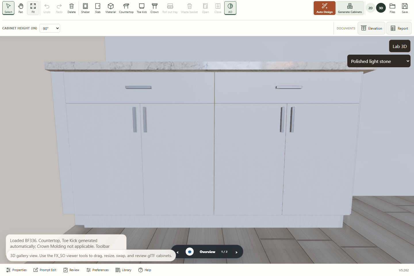
Navigate and select
Desktop
- Left-drag empty space to orbit.
- Right-drag to pan.
- Wheel or middle-drag to zoom/dolly.
- Click a cabinet to select it.
- Ctrl/Cmd + click for multi-select.
- Shift + drag a selected cabinet to relocate it in the same run segment.
iPad
- One-finger drag on empty scene: orbit.
- Two-finger drag: pan.
- Two-finger pinch: zoom.
- Tap cabinet: select and open the Adjustment Planner.
- Use Fit or the bottom camera-view arrows if the scene becomes difficult to navigate.
Edit the countertop contour and seating overhang
- Click or tap the countertop in 3D. Its connected outline turns blue, with edge dimensions and overall size. The selected edge is orange.
- Drag an exposed outline edge outward to add seating overhang, or select the edge and enter Extra overhang (in), then choose Apply. Decimals and fractions such as
12 1/2are accepted. The value is additional distance from the original contour. - Dragging uses 1/4-inch steps. Enter a value for finer adjustment. The wall-adjacent part of a short-wall edge stays fixed while its exposed portion can extend. Sink and cooktop openings remain protected.
- Use Reset edge to restore that edge, Esc to cancel an active drag, and Done to hide the editor. Save File retains the edits in the editable project. Regenerating the same countertop layout keeps its overhang edits; review them again after changing the cabinet footprint.
3D toolbar reference
| Tool | Operation |
|---|---|
| Open / Close | Animate supported cabinet doors and drawers. Use Close before final screenshots, elevations, or a client presentation. |
| Shaker / Slab | Change the active door style across supported cabinet fronts, fillers, and finish panels. |
| Countertop | Regenerate countertop slabs, exposed-end overhangs, and corner connections from the current cabinet layout. LS3612 remains a true L with its inside cutout open and the same exposed-front overhang on both legs. Click a generated slab to expose supported edge-drag handles; edge movement snaps in 1/4" increments. |
| Toe Kick | Regenerate toe-kick runs, exposed returns, and angle-corner joins. LS3612 follows both perpendicular recessed backing faces; BCF3 remains without a toe kick directly beneath its 3" × 3" filler body. |
| Crown | Regenerate the depth-aware 3" traditional crown profile across aligned Wall/Tall cabinets and compatible fillers, including supported end/corner returns. |
| Roll out tray | Select a compatible cabinet first, then add the tray accessory. The button is disabled when nothing compatible is selected. |
| Waste basket | Select a compatible B15 or B18 cabinet first, then add the waste-basket accessory. |
| Elevation | Generate dimensioned wall-elevation sheets from the current live 3D scene and download them as SVG. |
| Report | Open the live item list with cabinet/appliance quantities, codes, actual dimensions, style, finish, and layout item numbers; Download CSV or Print. |
| Frame debug | Toggle inferred cabinet origin/front/right frame diagnostics. Use only to diagnose a rotated, mirrored, or misplaced model; turn it off for presentation. |
| 2D / 3D | Switch the viewer presentation/projection while retaining the loaded kitchen. This control is inside the 3D ribbon and is separate from the planner's main 2D/3D switch. |
| AO | Toggle ambient occlusion. Subtle/Balanced/Strong changes contact-shadow intensity; Balanced is the normal review setting. |
| Fit / + / − | Fit the complete kitchen or zoom in/out. Fit is the safest recovery when the model leaves the visible scene. |
| Camera views | Use the bottom previous/current/next controls to cycle prepared views. Click the current view name to reapply that camera after manual orbit/pan. |
Create and download dimensioned wall elevations
 1234
- Generate the complete 2D cabinet plan, switch to 3D, and wait until the viewer says the toolbar actions are ready.
- Regenerate Countertop, Toe Kick, or Crown first if those components changed after the viewer opened.
- Click Views → Elevation. V5.238 creates one or more dimensioned wall sheets from the current live 3D cabinet records.
- Read Wall/Tall cabinet widths above each elevation and Base/appliance widths below. Confirm cabinet codes and the OVERALL run dimension.
- Verify the vertical chain: toe kick, Base height, countertop thickness, clear space, Wall cabinet height, and molding. Imported/custom room height remains separate from the active cabinet-system height.
- Scroll inside the dialog to review every wall elevation. The run-axis/facing note identifies the wall direction used for each sheet.
- Click Download SVG for the vector drawing, or Close to return to the interactive model. Regenerate the elevation after any later cabinet, height, countertop, toe-kick, or crown change.
Use the remaining 3D features
- Cabinet and Door Style: use Open/Close to demonstrate supported moving fronts, then apply Shaker or Slab. Close fronts again before final documentation.
- Finishing: use Countertop, Toe Kick, and Crown whenever cabinet geometry changes. Inspect normal corners, BCF3 joints, exposed ends, islands, and peninsulas for gaps.
- Accessories: click a compatible cabinet in the scene before choosing Roll out tray or Waste basket. Disabled buttons mean the current selection does not support that accessory.
- Tools: turn Frame debug on only when diagnosing cabinet orientation or frame inference; turn it off after the model is corrected.
- View: use the viewer's 2D/3D presentation buttons, AO toggle and strength, Fit, zoom controls, and bottom camera switcher. On desktop, orbit/pan/zoom with the mouse; on iPad use one-finger orbit and two-finger pan/pinch.
- Review: use Report after the final visual check, then download CSV or Print. Compare the schedule with the 2D plan and Elevation dimensions.
Adjustment Planner

- Click a cabinet in 3D.
- Choose a compatible item under Cabinet Swap, or keep the current type.
- Choose the target Kitchen Height when required.
- Optionally enter an instruction in Type Your Prompt Here.
- Review the read-only generated prompt, then click Apply Prompt.
- Use the Selection panel below for UID, dimensions, components, Frame Selection, and Frame Cabinet.
Review and report

12. iPad and touch workflow
- Open the same V5.238 planner. No separate iPad project format is required.
- Use the compact Floorplan, Zones, and Cabinets stage icons in the top ribbon; their accessible names remain available to assistive technology.
- Use the responsive bottom rail to open File or select Room, Openings, Runs, Functions, Corners, or Preferences; tap Prompt Edit there to open the prompt editor.
- Use one finger for taps, function dragging, and placement endpoint resizing; these layout edits remain in Zones. Use two fingers for plan pan/pinch.
- Keep the tablet in portrait for detailed form editing or landscape for a wider plan/3D view.
- In 3D, use one finger to orbit and two fingers to pan/pinch.
- Choose File → Save File to save the same
.kitchen.jsonproject used on desktop/web.
13. Final review checklist
Before 3D
- Enable Show design review overlay; resolve every pink error and review every amber item against the customer brief.
- Room dimensions and wall height are correct.
- Doors, windows, openings, and sill heights are correct.
- Base/Wall zone starts, ends, and depths are correct.
- Sink, stove, fridge, island, and tall intent are correct.
- RTA or Custom mode is intentional.
- RTA cabinets use supported catalog widths and 1 1/2"–3" fit fillers, or each Custom odd segment contains only one reduced balancing cabinet.
- Corner ownership, handedness, fillers, and exposed panels are correct.
- Peninsula/island fronts face the intended direction.
Before handoff
- Countertop covers the complete supported layout without gaps.
- Toe kick connects through normal and angle corners.
- BCF3 is attached to both cabinets and has no toe kick underneath.
- Door style/finish also applies to fillers and finish panels.
- Report quantities, source codes, actual widths, and dimensions match the 2D plan.
- The editable design has been saved.
- Planner JSON/CSV/print output has been produced if required.
14. Troubleshooting
Design findings remain after generation
I cannot place a zone or opening
A corner cabinet will not place
I selected Blind L/R but the result looks reversed
The blind cabinet moves when I try to resize it
Dropping LS3612/WDC2436 created no replacement
My Base did not become a peninsula
My island attached to a wall
Joyplan DAE will not import
.dae, and wait for conversion. If conversion still fails, use a verified GLB with Open GLB Floor Plan or correct/re-export the Joyplan DAE.The filler or panel looks wrong
The refrigerator end panel overlaps the next Wall cabinet
REP96 return panel. The Wall solver now reserves that 3/4" interval before sizing cabinets—exactly as the Base row does—so the adjoining Wall cabinet keeps a normal body width and begins at the panel's outside face. It must touch the panel with no gap or pink overlap. Reopen 3D and confirm the same panel is visible there.A Wall blind-corner filler is missing in 3D or Crown crosses the corner
WF3X36 beside the WBC; the next Wall cabinet must begin after it. Click Crown again after regeneration. The two crown runs should form one clean inside-corner join without crossing return pieces.I cannot see the BF336/BCF3 switch
BCF3 does not show a 27" × 27" setback
RTA created several narrow pieces
The Custom cabinet code is wider than its displayed dimension
Switching RTA/Custom changed many cabinet codes
I cannot see Tall Cabinet / Fridge / Appliance
Appliance is disabled for my Tall cabinet
The Tall cabinet will not resize or swap
Elevation is empty or missing a wall
A 3D toolbar action is disabled
The 3D view is too dark, too close, or off-screen
Generated cabinets no longer match my intent
3D is empty or incomplete
I lost the plan or camera position
I need to continue on another device
.kitchen.json project. Open the same file from the File menu on the other V5 planner.Socket and Fridge: Drag Socket from the Room tools onto a wall near the desired run end. The fridge snaps to that usable Base run end, retaining wall clearance and end-panel space. Generate Cabinets creates a missing fridge or reuses the existing one; Auto Design follows the socket wall and end. A blocked end is reported. Select Socket to edit its wall-end dimensions or delete it. Socket supports save/open and Undo/Redo.
Water and Gas: Drag these Room tools onto a wall. Select the symbol and click either wall-end distance to edit its center position (fractional inches supported). Properties also offers both distances and Delete. Generate Cabinets automatically creates missing Sink and Range functions at Water and Gas points, then fills surrounding cabinets. Repeated generation reuses the existing functions. Sink and Stove/Range centers may be up to 6 inches either side of their Water/Gas symbol along the same wall. Auto Design and Generate Cabinets may use this tolerance to improve the layout and cabinet fit. Symbols retain their measured positions, and generated cabinets follow the chosen function positions. Unavailable alignment is reported. Service points save with the design and support Undo/Redo.
Elevations: Light shading and clear outlines show cabinets, appliances, countertop, toe kick and crown. Doors, windows and openings appear at their measured positions and sizes on occupied elevations. Empty walls and filler-only groups are omitted. Dimensions and cabinet labels remain visible; SVG exports use the same style.
Elevation drawings remain available while the 3D panel is hidden. Returning to a view reuses its cached drawing; finish-color changes do not rebuild neutral elevation lines. Island dimensions include the countertop and omit wall crown molding.
Elevation names and corners: Select Sink, Stove, Fridge, or combined function names such as Sink Fridge. Island and Peninsula are identified separately. Blind, diagonal and L-shaped corners appear in both adjoining elevations, with their real projected side faces. Filler-only and empty walls are omitted.
Fridge at a corner wall: A measured 1–3 inch clearance is accepted without an unresolved cabinet-gap warning. Freestanding fridges leave this strip open.